Whew! Until yesterday, when I sat down to write this, I had not realized that the last time I blogged about building my Bede BD-4C airplane was way back on September 5 (Roof Ribs) and the only time that I wrote about the wiring was on August 30 (Airplane Wiring Diagrams). I have actually been working on the plane; it is the blogging that I have neglected. My photography and writing have been directed at the AeroElectric-List, an invaluable resource for anyone working on airplane electrical systems.
I have built the wiring harness that runs through the inside of the spar, because those wires need to run down through the square channels on the sides of the fuselage. It was much easier to install those wires before the roof. Here is what I created.
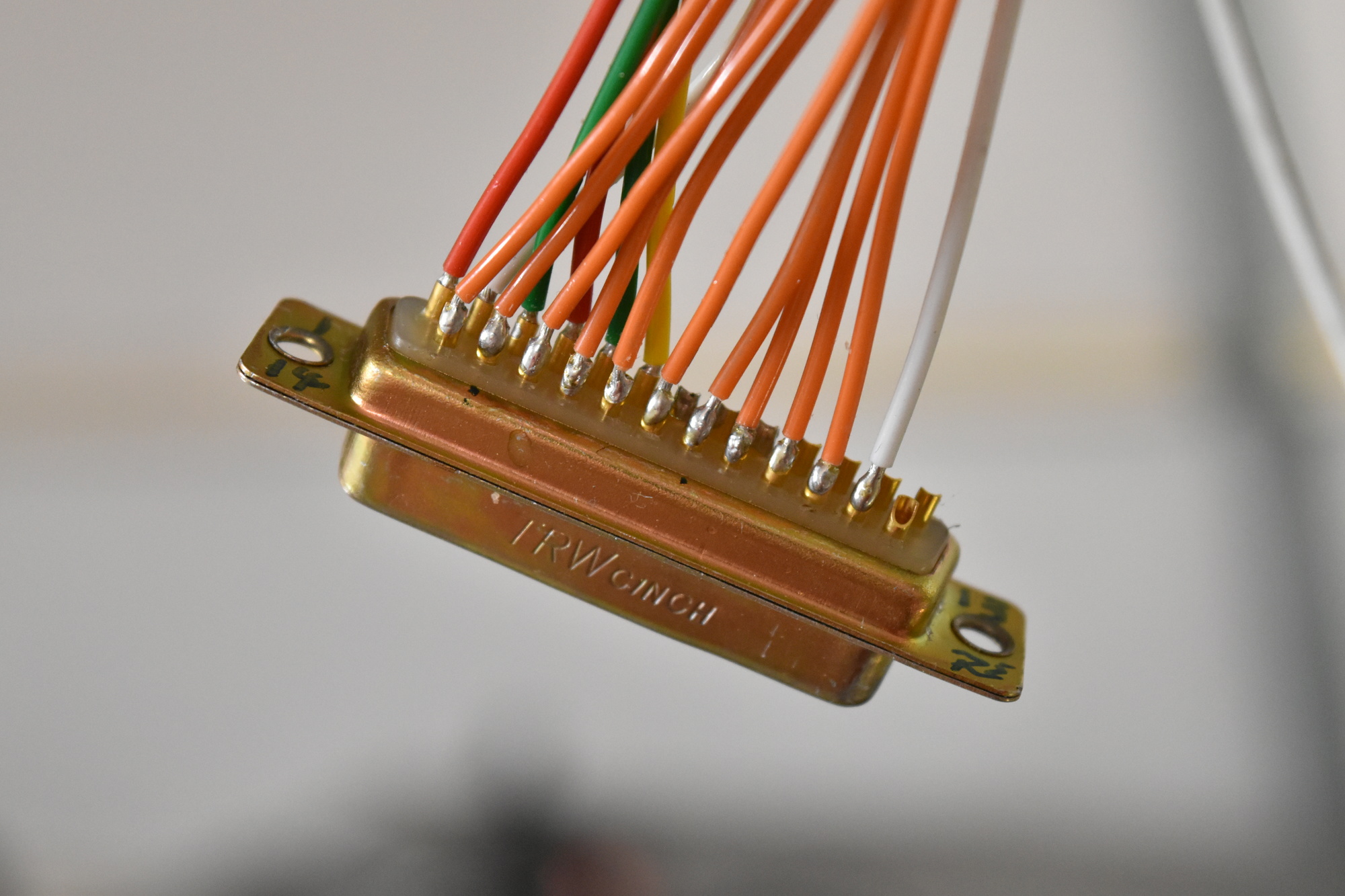
I used a DB-25 connector instead of something more exotic because it fits the mission perfectly. It is sturdy. Each pin can carry up to 5 amps. Parts are readily available and whole connectors are easily replaceable.
As with the rest of the wiring, I considered crimp pins but, in the end, I decided to try soldering. Had it not gone well, all I would have wasted was some time and a few cents on a connector. I would then have purchased crimp pins and a crimping tool. I messed up a lot, re-soldered just as much, and learned a ton. Ultimately, I ended up with connections that please me, looking clean and safe. Here is a close-up of the connector for the left wing. The wires on the row closest to the camera run the navigation/position/strobe lights and landing light. Click this photo (or any other) to see larger version.
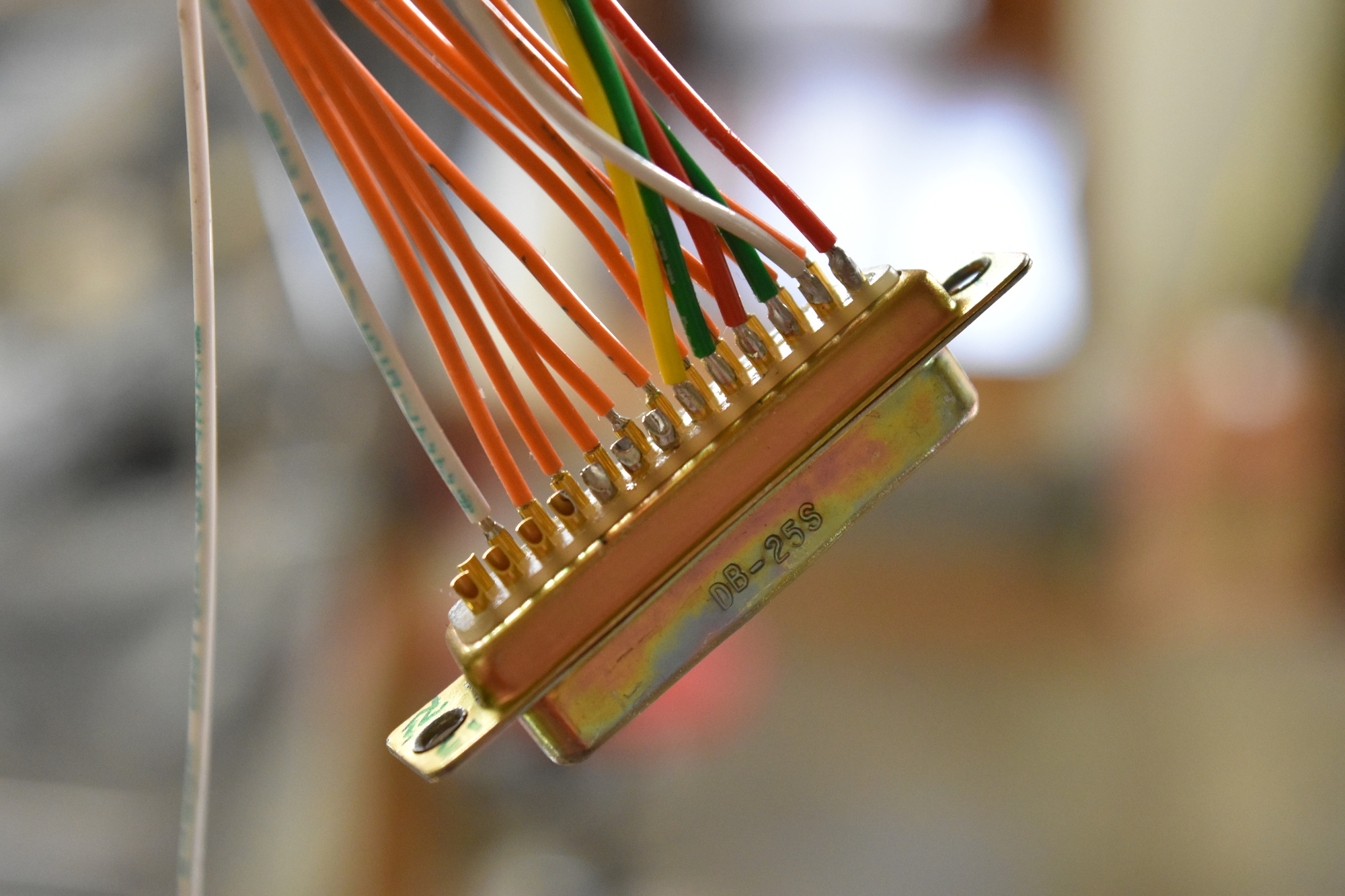
Since I am using LED lights, all of these devices draw very little current and a single pin in the DB-25 connector was sufficient for each circuit. I will also install the pitot tube in the left wing. The pitot tube heater draws up to 15 amps, whichis way more than the 5 amps that each pin can carry.
The “fix” is to split the heater circuit into five pins, each carrying 3 amps of load. Bear in mind that this is five pins for the red wire and another five pins for the black wire; 10 pins total. Plus a pin for the heater monitor circuit.
When splitting the load across multiple, parallel pins in the same connector, you need to assure that an equal portion of the current goes through each pin. It would not help at all to wire five pins if all of the current went through just one of them. Bob Nuckols worked out the solution. This is from an email Bob posted to the AeroElectric list on September 22, 2016. The short version is: assure that each pigtail is composed of 12 inches of 22 AWG wire, 6 inches on each side of the connectors. The long version is,
22 AWG is 16 milliohms per foot. A single pin-to-socket interface on a D-sub can present 3 milliohms of resistance over a millimeter. Variability in resistance between pin-to-socket interface within a connector gives rise to the prohibition for paralleling pins to increase current handling of any one path.
I designed and qualified a paralleled D-sub pin process at Beech that was used in both targets and production aircraft. This involved extending each pin in a paralleled array with say 12″ of 22 AWG wire before the pin-paths were joined in parallel. This adds 16 milliohms resistance to each 1-3 milliohm pin-to-socket variability. This ‘ballasting’ resistance forces the sharing of current across an array of paralleled pins.
The short answer is that concerns for heating due to current flow reside in the pins… not the wires.
Here is one “side” of the connector, on my workbench. The orange wires are the 22 AWG “ballasting” pigtails, 6 inches long. The other side of the connector also has 6 inch pigtails.
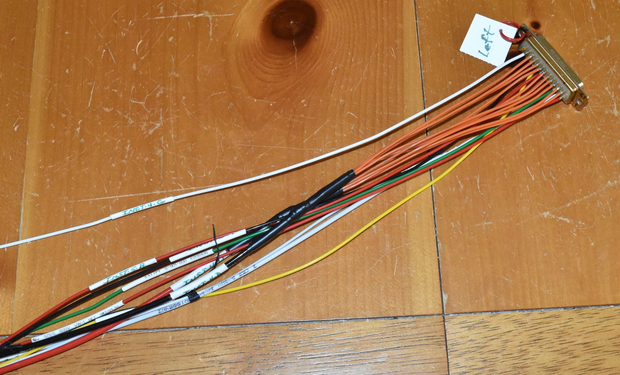
Inside the heat shrink tube, I split the 12 AWG wires into five 22 AWG pigtail wires. It looked like this:
Here is the flip side of the connector pictured above. For convenience, I used the pins on one side for the pitot heater and the pins on the other side for everything else.
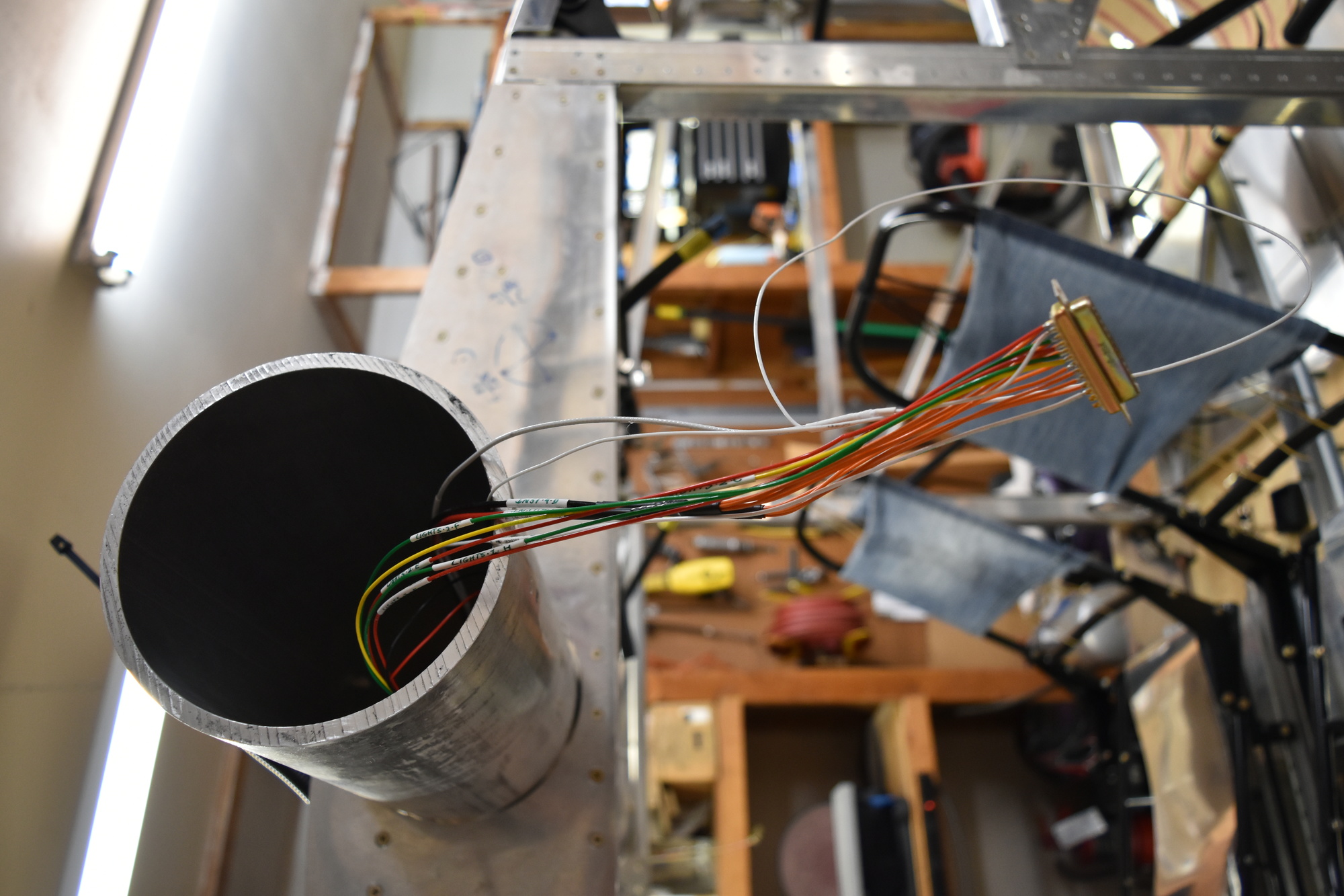
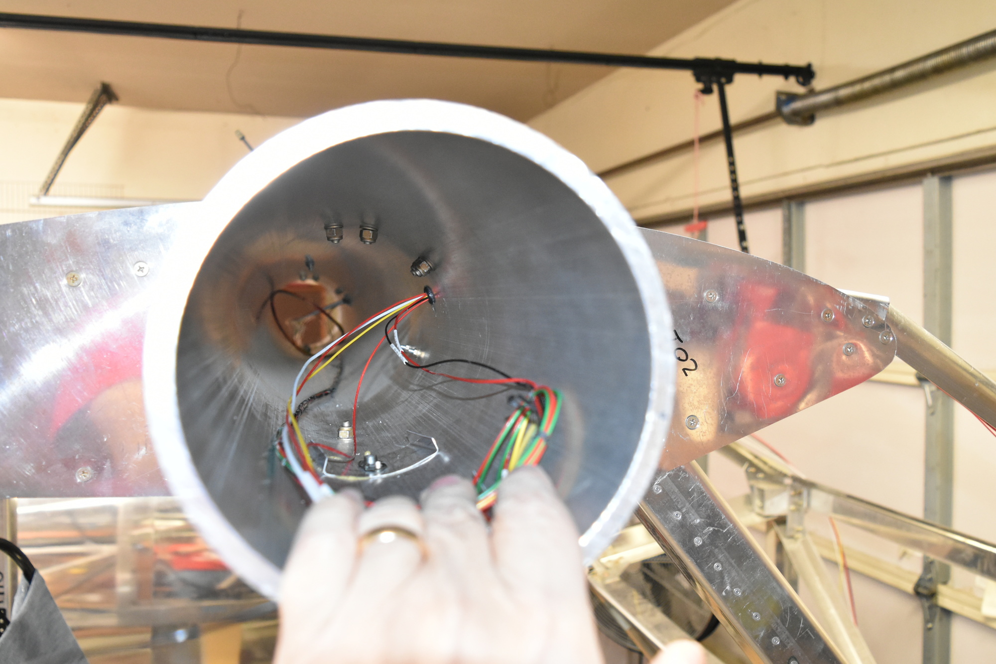
The wires run through the wing inside the spar. There are DB-25 connectors where the wing attaches to the fuselage, which gets the wiring inside the center section of the spar tube. To get the wires out of the spar tube, I drilled holes, chamfered the edges a bit, and installed grommets. Since I could not find grommets locally that were thick enough for the 0.3 inch thick spar tube, I sliced regular grommets in half and bonded them to the holes with silicone sealant. Peering into the right end of the spar, you see this:
Here is a close-up of the wiring and the grommet.
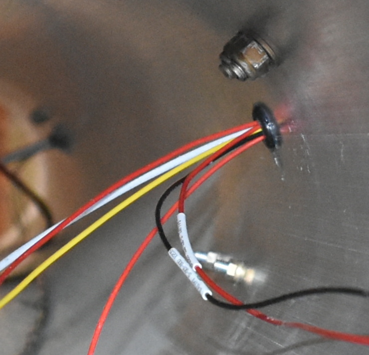
Outside the spar, the wires run through a piece of corrugated conduit inside the square channels at the front of the cabin. The loose red, black, and yellow wires are for the fuel level sensors, located inside the fuel tanks. Due to the geometry of the spar inside the wing, I could not get those wires to the same DB-25 connector. They will have their own connector outside the spar.
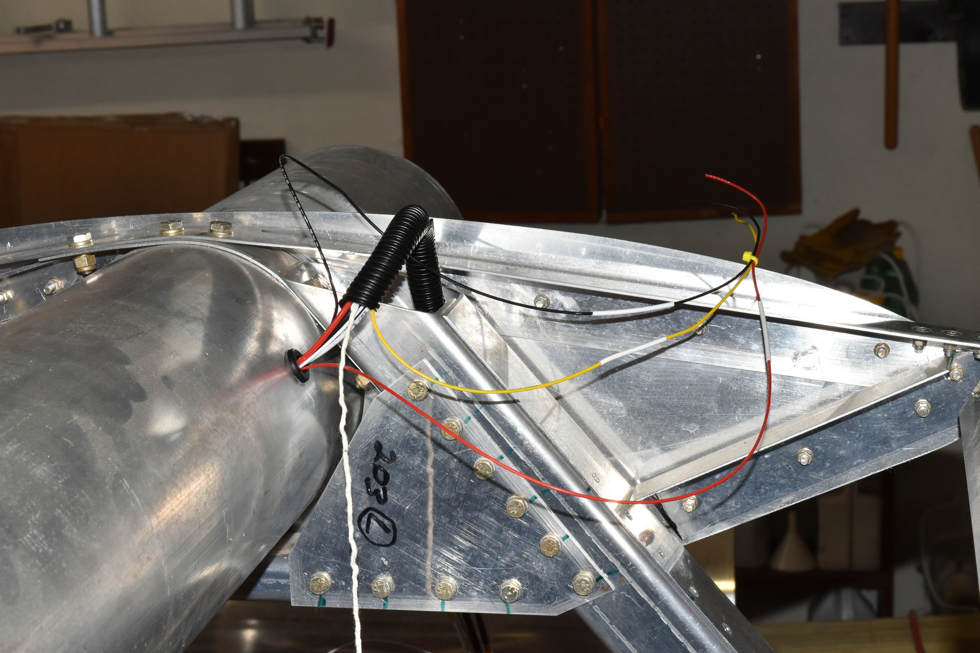
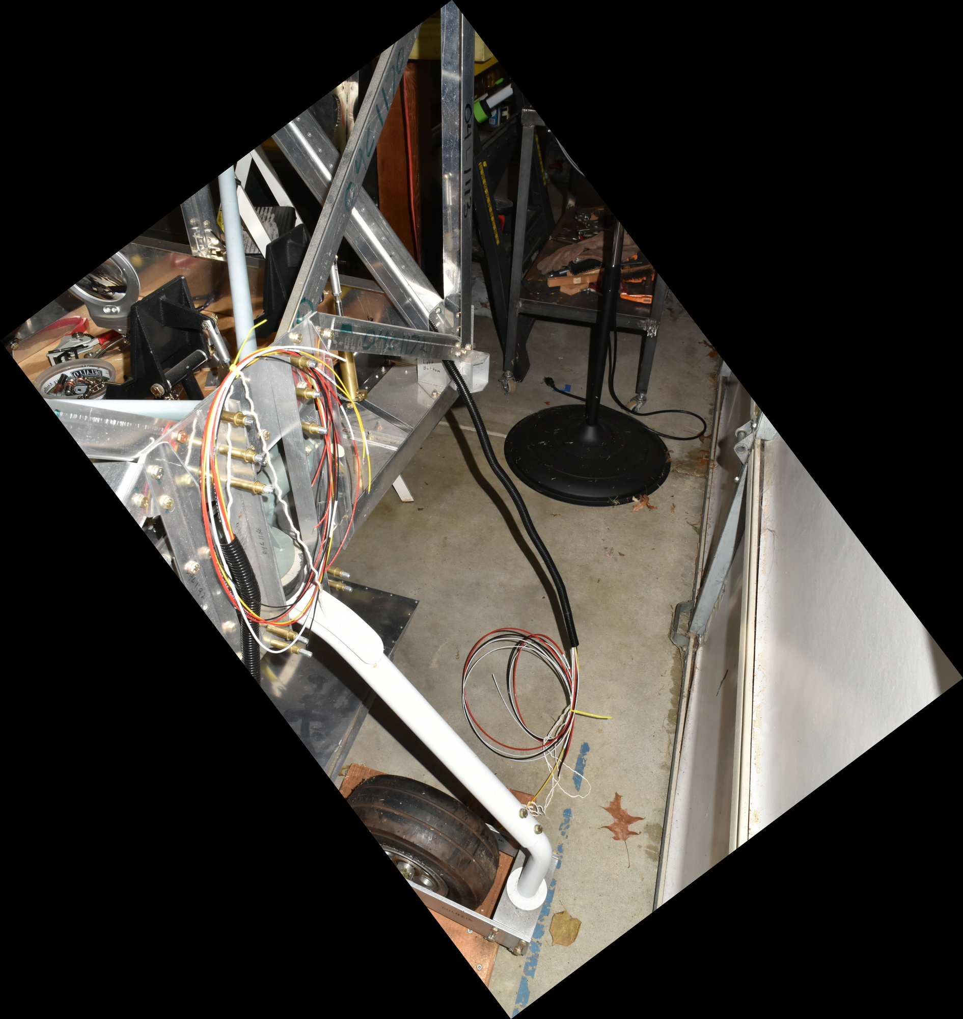
Here is a photo of the wires hanging out of the bottom of the square channel, with plenty of slack to allow routing them behind the instrument panel and connecting them to instruments, switches, and ground lugs.
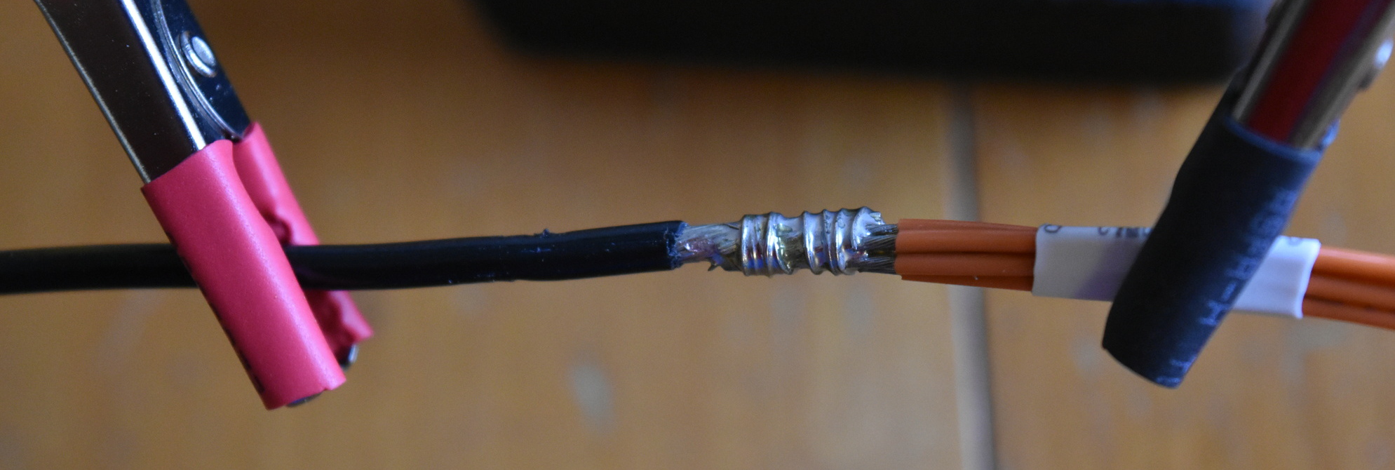
I dealt with another interesting challenge with the power wire for the strobes. The manufacturer (AeroLEDS) recommends shielded wire, which is readily available but tiny compared to the last shielded wire that I worked with: RG-59 coax for television. I needed to solder a wire to the shield so that I could ground it. Surprisingly, it was easy to solder.
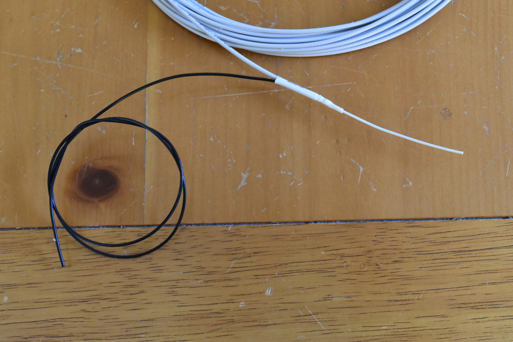
First, I stripped the outer insulation off of the shielded wire and trimmed the shield back. I laid the ground wire next to the shield and wrapped a strand of bare wire around them to create a tight mechanical connection. A bit of solder fixed everything permanently without melting the insulation inside the shield (around the center conductor). It looked like this:
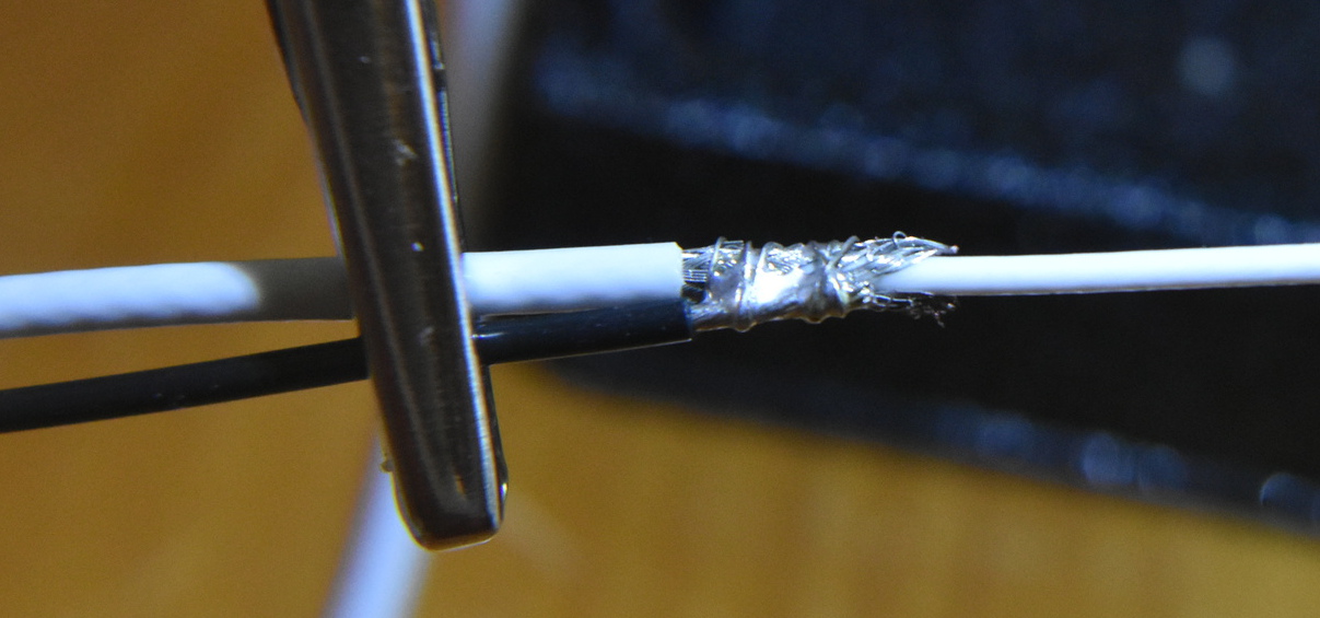

I added two layers of heat shrink tubing for strain relief and here is the result:
Not pictured are the other two thirds of the wiring harnesses: one piece to run through each wing.
Next up: installing brackets to hold the conduit in place at the top of the square channels. I also need to install the housings on the DB-25 connectors.

Looks good. I used soldered wire also. I did cover all soldered joints with shrink to afford some flexing restriction. That was back in 1984 and no breakage to date. The FAA says to crimp due to flexing causing breakage.
Keep up the great work! Maybe we will see you and it at Air Venture 2017!