Since I last wrote, I have spent a busy couple of weeks making good progress on four subsystems of my Bede BD-4C: brakes, rudder pedal tubes, instrument panel support, and control stick torque tube brackets. It is nice to have both the time and the parts necessary.
First up was installation of all four brake master cylinders. In case you missed it, I posted a short video showing how one set of rudder pedals operates both the rudder and the brakes. With the master cylinders in place, I installed the brake line fittings. I also drilled holes through the nose gear structure, and installed grommets in the holes, so that the brake lines can run between the two sides of the cockpit.
I was startled to see how small the brake line is, just a 0.125 inch outside diameter plastic tube. I am used to seeing the metal brake lines on cars and I wondered if the airplane brakes somehow operated at relatively low pressure. Not so. Looking up the Parker NR series semi-rigid, high strength tubing, the stuff in my plane is rated for 625 psi working pressure and a minimum burst pressure of 2,500 psi. Best of all, the entire length of brake line tubing for the whole plane weighs less than two ounces.
I removed the rudder pedal tubes again, trimmed one of them a little shorter so that it would move more easily, and touched up the paint on both of them. With all of the work, they had gotten dinged up in several places. Even more important, there was bare steel showing where I had shorted the tubes with the disc sander.
I needed to added a piece of aluminum angle to the fuselage. This one runs across the cabin and will support the top of the instrument panel. (Click on any picture to see a larger version.)
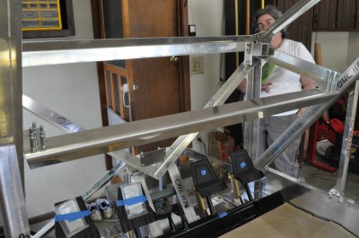
Though a simple project, it was pretty satisfying because I got to be “creative;” there are no drawings of the gussets for attaching this angle to the plane. Using photos of BedeCorp’s BD-4C, I “winged it” and created my own gussets. Here is a picture of one, part way done.
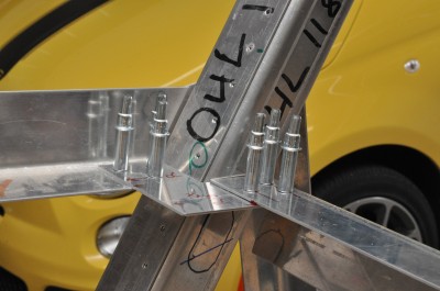
As part of finishing the gusset, I trimmed off the corner closest to the camera. Got to save those ounces, you know!
With the paint drying on the rudder pedal tubes and the instrument panel support in place, I turned my attention to mounting the torque tube at the base of the control sticks. This tube operates the controls for both the ailerons and the horizontal stabilator. Way back in January, I had made the CS-9 and CS-10 brackets to hold the torque tube. This involved drilling 1.125″ holes through the brackets and through the Micarta blocks. This weekend, it was a royal pain in the proverbial donkey to get all of the parts lined up. It would have been much easier to bolt all three parts together (CS-9, CS-10, and Micarta block) and then drill the 1.125″ hole through the set. Next time….
I am happy with the result, though. Here is the bracket holding the copilot’s end of the torque tube. The copilot’s control stick will attach to the tabs on the right side of this photo.
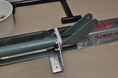
And here is a photo of the torque tube, set in position on the floor of the cabin.
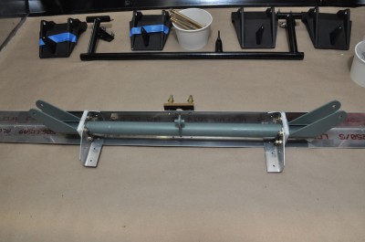
The push-pull rod for the horizontal stabilator will attach to the tab in the middle. The cable for the ailerons will run through the tube and the bottoms of the control sticks will be able to pull that cable left and right.

BEAUTIFUL!