Light airplane brakes are hydraulic, like car brakes, but they are arranged a little bit differently. There are four rudder pedals in most airplanes, two for the pilot and two for the copilot. To move the rudder, you push on a pedal. To activate a brake, you push on the top of a pedal, tilting it away from you. The left pedal operates the brake on the left main wheel; the right pedal operates the brake on the right main wheel. Since you can apply brakes to either wheel independently, you can turn an airplane an a pretty tight circle.
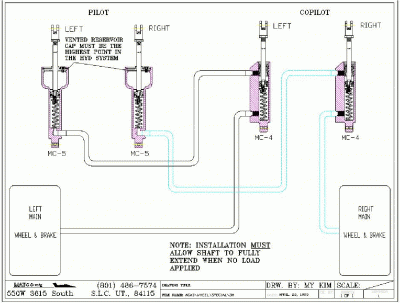
BedeCorp supplies Matco brakes and master cylinders with the Bede BD-4C kit. There is one master cylinder attached to the back of each of the four rudder pedals. Each of the master cylinders behind the pilot’s pedals has an integral brake fluid reservoir. The cylinders behind the copilot’s pedals are “slaves” and do not have the reservoirs. Here is a diagram of how the plumbing gets hooked up, which will probably make it more clear than my words. (Click on the picture to see a larger version.)

I have been working on the brackets which will hold the bottoms of the four brake master cylinders. These brackets attach to the floor, between the rudder pedals and the firewall. Since there are several other structures already there, I had to create a dozen shims of various thicknesses and sizes to “even up” the floor so that each bracket will have a level surface on which to sit.
Once I got all of the shims made, I taped everything into position with “magic blue aviation tape.” You may have seen a similar product in the paint department of your local hardware store. The stuff that I bought looks suspiciously like the blue masking tape in your local hardware store but, since I am using it on an airplane, I am quite sure that it is aviation tape and not plain old blue masking tape.
Anyway, between the masking aviation tape and a little help from Candy’s hands, I got all of the parts (12 shims and eight brackets) to hold still long enough to drill the holes for the bolts. There are three bolt holes in each bracket so it took awhile to get it all drilled.
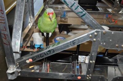
Here is a photo of the brackets in front of the copilot’s pedals. Robin Hood is sitting on top of the tube to which the copilot’s right pedal will be attached. If you click on the picture, you will get a larger version and it will be easier to see the brackets, attached to the floor at the bottom of the photo.

Once all of the drilling was done, I removed all of the brackets, shims, nose gear structure, and the black-painted pieces for the rudder pedals. There were aluminum shavings all over the place from all of the drilling. The only way to clean that up was to remove everything and use the vacuum cleaner.

Show Robin Hood this video. Then have him recruit more friends. First flight by next weekend!! http://www.youtube.com/watch?v=UoR-dgHT0Io&feature=youtube_gdata_player
Great idea, Paul. Why didn’t I think of that?