I spent the whole week working on various aspects of the rudder pedals and controls for my Bede BD-4C. I cut the steel rudder pedal posts to fit the rudder pedals, drilled the tabs on the backs of the pedals to accommodate the hinge pins, Alodined and painted a few parts, drilled the fuselage for the rudder cable guides, and drilled the brackets for the rudder bell crank at the back of the fuselage.
Cutting Down the Steel Rudder Pedal Posts
First up was to shorten the T’s at the tops of the rudder pedal “posts” so that they would fit between the tabs on the backs of the actual pedals. I used a cut-off wheel and my 12″ disc sander to cut the steel, which made quite the shower of sparks and thoroughly “entertained” Candy, which is to say, she hid in the house ready to call the fire department in case I set the garage on fire.
When I got done cutting and sanding, the ends of the tubes were a mess. I had Candy take pictures of the clean-up process so you could see a couple of the tools that I have been using. (I have lots of pictures for you this week. Click on any of them to see larger versions.) First, the mess. I had drawn cut-lines on masking tape. When I peeled off the tape, the end of the tube was all jagged and the primer was wrecked from the heat generated by the cut-off wheel.
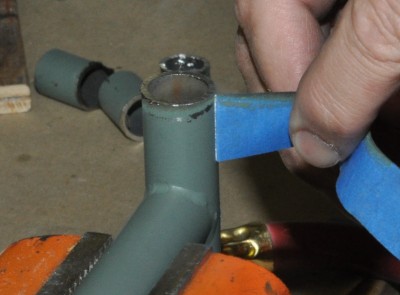
I started by deburring the inside of the tube. It only takes a couple of turns with this tool to debur aluminum. Steel was tougher, it took about a half dozen turns.
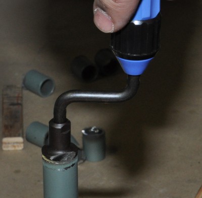
For the rest, I did the manly thing: I got out a power tool! I used a pneumatic die grinder with a small Scotch-Brite wheel.
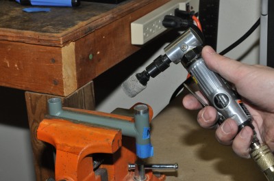
I ran the wheel around the outside edge and then flat across the top.
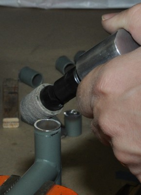
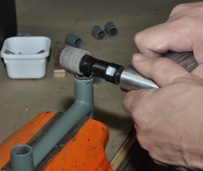
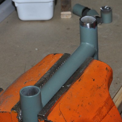
The die grinder made quick work of the eight cut ends. Here is one, all cleaned up and ready to be repainted.
Drilling the Hinge Holes in the Rudder Pedals
The rudder pedals have tabs on the back but, when I received them, there were no holes in the tabs for the hinge pins. I got to drill them which meant finding a drill press with at least 3.75″ of travel and some long drill bits.
I am a member of EAA Chapter 32 and, fortunately, the chapter has a couple of drill presses and one of them is plenty big enough for this job. I cannot imagine building a plane without the resources of my EAA chapter. No matter what problem stumps me, there are sure to be several people in the chapter who not only know the answer the are willing to teach me. It is a money-saving bonus that the chapter also has tools that I can use.
Here is a finished rudder pedal with the hinge pin in place.
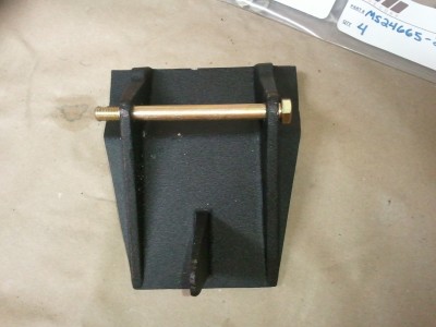
The first challenge in drilling these was how to hold them still and perpendicular to the drill press table, since the pedals do not have any square edges. I hit upon the idea of clamping the pedal to an iron pipe, which worked beautifully.
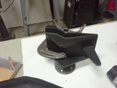
It was easy to hold the base of the pipe jig still on the drill press table. It looks like I am about to drill into my hand but I adjusted the press so that the bit could not reach down to my fingers.
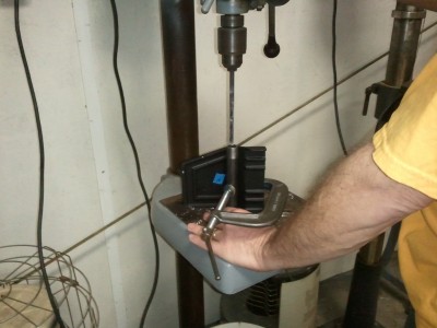
I drilled each pedal in several stages, staring with a small drill bit, then a medium one, then a 5/16″ bit, and finished up with a 3/8″ reamer. The result was a pair of holes nicely aligned.
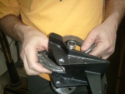
Alodine Again
Sunday was great weather so, for the first time since I got the Bede BD-4C kit, I spent the whole day working with the garage door wide open. I love spring!
I started the day by applying Alumiprep and Alodine to the brackets to which the rudder pedal posts will be attached. These will be visible on the floor so I want them to look good in gloss black and to be well protected from water that might get carried into the plane on people’s shoes.
I diluted the Alumiprep approximately 1:5, since all the metal is pretty clean. I diluted the Alodine approximately 1:3. At these concentrations, both processes took several minutes and were easy to control. It was a much better experience than last time, when I used both chemicals full strength. Here is the result.
Once the Alodine dried, I spray painted everything black. No need for the paint booth this time; we had gentle breezes and warm weather so I just took the parts outside.
Rudder Cable Guides
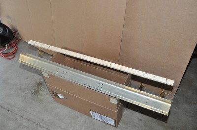
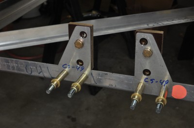
The rudder is activated by a pair of cables that run the length of the airplane. The cables go through six sets of guides, four free-standing ones and two that are integrated into the walls of the main gear box. Back in January, I had fabricated the brackets for the guides. Today, I drilled the fuselage so that the guides could be attached. Everything is held together with clecos for now. I still need to remove stickers from various parts and clean off a lot of Sharpie marks before final assembly with bolts and lock nuts.
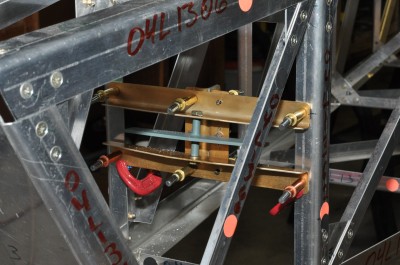
Here are the guides.
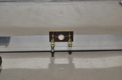
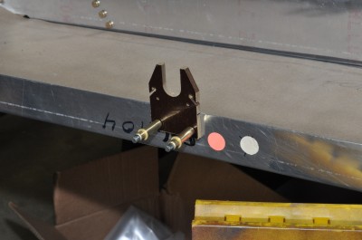
The third guide for the rudder cables is fastened to the brackets for a bell crank that “joins” two push-pull rods. The steel push-pull rod for the horizontal stabilator runs through the front of the fuselage. Just behind the back seat, it “turns into” an aluminum push-pull rod, which runs the last seven feet to the tail of the plane. This bell crank supports the joint between the two rods.
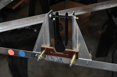
The fourth guide is about four feet from the tail of the plane. The rudder cables will run through one pair of holes. The horizontal stabilator trim cables will run through the other pair. The large diameter aluminum push-pull rod will run through the gap between the brackets.
Rudder Bell Crank
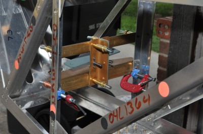
The last job of the day, which took a couple of hours, was to drill the holes in the brackets for the rudder pedal bell crank. The rudder cables terminate at this bell crank and a short push-pull rod runs out to the base of the rudder. The plans for the Bede BD-4C give the location of the holes in the top bracket. Everything else needed to be drilled to fit so the process was a matter of slowly fitting one part and then measuring where the holes for the next needed to go, drilling those holes, and repeating for the next part.
Congratulations. If you are still reading at this point, you certainly deserve a prize! Thank you for sticking with me.

REALLY, REALLY BEAUTIFUL!
BOB.