I chose to build a Bede BD-4C airplane in large part because it is a very simple airplane and simplicity correlates highly with reliability. Most of the time. On a recent flight with Steve, I had been proudly bragging about how I had installed dual alternators on my airplane for extra reliability. Less than 30 minutes later, both alternators failed, leaving the airplane with only battery power for the remainder of the flight.
As they say: To make God laugh, tell Him your plans.
Steve and Paul and I had flown to Sikeston, MO to have lunch at Lambert’s Cafe. I had noticed that the voltage on my EFIS screen was only 13.1 volts, instead of the normal 14.5 volts. Looking at the right side of the instrument panel, I could see that the circuit breaker for the primary alternator’s field had popped. This can happen and, as long as it is infrequent, it is not a big deal. Resetting it in flight – once – is normal procedure when it pops. The breaker was easy for Steve to reach, so I asked him to reset it, which led us to a discussion of the electrical architecture of my airplane.
After landing and dropping off Paul, I restarted the engine, taxied to the runway, and did a run-up. Everything checked out normally. Part way down the runway during the takeoff roll, the EFIS displayed a red warning: SUPPLY VOLTAGE LOW. I decided that this was not critical enough to warrant aborting the takeoff so I continued. Once airborne, and in level flight, I tried to fix the problem:
- I turned off and back on the switch for each alternator.
- I checked that the circuit breakers for the alternators had not popped.
- I had Steve pull and and then reset each circuit breaker.
This confirmed that neither alternator was working and neither was coming back to life during the flight. I opted to continue flight to my home airport, Smartt Field, which was only about 15 minutes away. I knew that the battery had more than enough energy in it to run the lights and the radios and the EFIS for that short flight.
Dual Alternator Architecture
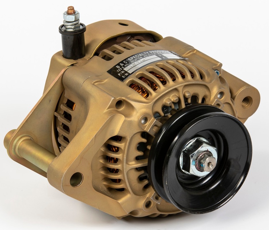
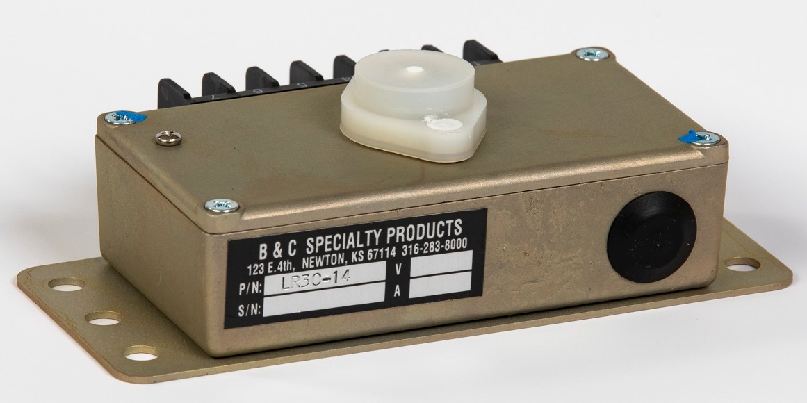
My BD-4C’s primary alternator is mounted on the front of the engine and driven by a rubber belt, just like the alternator in a car. (As a matter of fact, the belt is a belt from a car.) The alternator is controlled by an external voltage regulator, a small box mounted inside the cockpit. The voltage regulator is set for 14.5 volts. When the bus voltage falls below 14.5, the regulator makes the alternator generate power, raising the bus back to 14.5 volts. The primary alternator can generate up to 60 amps, more than enough to run all of the devices in the airplane and simultaneously charge the battery.
The backup alternator is mounted on the rear of the engine and driven by a gear. Since I do not need a vacuum pump in my airplane, I re-purposed that spot on the engine to mount a second alternator. It is controlled by a second voltage regulator which is set at 13.1 volts. The backup alternator can generate about 30 amps, enough to run everything except the pitot tube heater (which is rarely required: only when flying in rain, snow, or clouds and when the temperature is below 40 degrees Fahrenheit).
I fly with both alternators turned on all the time. If the primary alternator fails, the bus voltage falls to 13.1 volts and the secondary alternator automatically starts generating electricity. If both alternators fail, the bus voltage falls to whatever the battery can provide, which is about 12.9 volts when fully charged, and drops slowly as the energy stored in the battery gets used up.
By glancing at the bus voltage on my EFIS screen, I can easily determine exactly how my alternators and battery are behaving.
I installed a switch for each alternator, allowing me to turn them on and off independently. This allows me to test the system and confirm that a) both alternators work as planned, and b) I see the right bus voltages displayed on the EFIS screen to confirm the correct operation. Every couple of flights, I turn off each alternator in turn and then turn both off together. Then I turn them both back on. I check that the airplane operates correctly throughout the test and that I see the expected voltages displayed on the EFIS screen.
Note that the Lycoming engine in my airplane does not require any external electricity to run. Once it has started and is turning, the dual magnetos generate their own electricity for making the spark plugs spark. It is perfectly safe to turn off all of the electrical devices in my airplane while it is in flight.
The Problem
In a moment, I am going to show you the wiring diagram for the engine compartment in my BD-4C airplane. It is pretty complicated so first I want draw your attention to just two wires so that you can easily understand what failed in my airplane.
I based my electrical design on Figure Z-12 from The AeroElectric Connection by Bob Nuckolls. This is a well thought out design for an airplane with two alternators and one battery. Toward the right side of the diagram, you will see two large rectangles labeled “ALTERNATOR CONTROLLER,” a synonym for what I have been calling voltage regulators. Each controller/regulator has a pin 3 labeled “OV SENSE,” which allows the regulator to sense when the bus voltage gets too high: over voltage (OV).
If you follow the wire leftward from pin 3 on each regulator, you will see that it goes to a 2 amp circuit breaker. I used fuses instead of circuit breakers in my Bede BD-4C but the basic function is the same.
Here is the diagram:
I took an unfortunate short cut when I built my airplane. I looked at those overvoltage sense (OV SENSE) circuits and assumed two things. First, I assumed that they would carry virtually no current so the fuse was highly unlikely to blow. Second, I assumed that the circuit was less than critical and that, even if the fuse blew, the alternator would still produce electricity.
I was wrong. The B & C regulators require voltage on pin 3. No voltage on pin 3 = No electricity from the alternator.
My dual alternator failure was caused by a single blown fuse. With no voltage on pin 3 on either voltage regulator, neither alternator produced any power. Diagnosis was hindered because I had not bothered to update the wiring diagram so, when checking the documentation, it did not look like there was a single point of failure on the OV SENSE circuits.
In summary, there were several problems which contributed to the dual alternator failure:
- A shared fuse for pin 3 on both voltage regulators.
- Inaccurate documentation. The wiring diagram shows independent fuses for pin 3 on each voltage regulator.
- Lack of knowledge on my part, which allowed me to share the fuse.
- Karma, which made this happen less than 30 minutes after I had been proudly showing off my dual alternators.
Kudos to TJ at B&C Aero. When I called to get educated on what pin 3 does and how the voltage regulator acts in response to 0 volts, he had already read my email on the aeroelectric mailing list and knew the background of my situation.
Kudos to B&C Aero for providing an excellent troubleshooting guide within the LR3C Installation Manual. Step 2 pinpointed the problem.
The Fix
Short term, I fixed the problem by replacing the blown fuse. The original lasted over a year and through more than 70 flight hours. I have no reason to believe that the fuse will blow again soon.
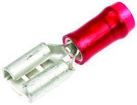
The real solution, which I will do within the next week or so, is to separate the two OV SENSE circuits, feeding each through its own fuse. This will be pretty quick since I already have two wires, one from each voltage regulator, running to the fuse block. They are crimped together into a single FASTON receptacle at the fuse block. I just need to cut off the shared receptacle and crimp on two new ones. Then I can connect each voltage regulator’s OV SENSE to its own fuse.

Great story and clearly explained.
So the fix will be one larger fuse, or two fuses? Or rewire to CBs in cockpit? Do you have blast tubes to cool the Altenators? Inquiring minds want to know.
The fix is to run each OV SENSE circuit to its own fuse. I just added that to the end of the blog post, too.
Hi Art!
…at least you got to ttest your battery!!
Question: WHY fuses instead of circuitbrakers??
Cheers,
Thomas
Cost and weight. There are no circumstances when I would feel it necessary to reset a circuit breaker in flight (except the 5 amp circuit breakers for the alternator fields). Since I don’t need to reset them in flight, fuses are fine.
this ret mechanic says, circuit breakers are the Only way to go when
you can’t pull over to the side of the road..sheer folly, nay, a novice’s hubris , prof Art…$6.00 x n = cheap LifeInsurance… cheers
https://millenniumconjectures.files.wordpress.com/2012/08/murphy.jpg
dar,
Your premise is that there are situations in which I want to reset a circuit breaker during a flight. My electrical system is designed so that I do not ever want to replace a blown fuse in flight. Were I to have circuit breakers instead of fuses, that would not change. I always want to land, replace the fuse on the ground, and see if I can identify the reason why it blew. Given my premise and design, circuit breakers do not increase either the reliability or the safety of my airplane.
— Art Z.
It’s great hearing about trouble and trouble-shooting, especially when there is a happy ending.
Thx for sharing this story, Art.
Great explanation and remedy Art! I guess I’m too much of an airline/big airplane guy, I like CBs that I can see and operate. (Yes, I have some non pull-able breakers in 43D that WILL get changed in the foreseeable future!)
You are in the majority, Jim. I may just be cheap but 24 fuses for less than a dollar each versus circuit breakers at about $6.00 each is a lot of money, not to mention the additional weight and panel space. I tucked my fuse block up underneath the instrument panel above the copilot’s knees.
I agree with your logic on the circuit breaker versus fuse issue. Circuit breakers, if they cycle often enough, tend to get “lazy” and that makes system troubleshooting more difficult. You never find circuit breakers in high amperage circuits.
The question I have is why did the problem take so many hours to manifest itself?