At long last, I am beginning to assemble some of the myriad small parts that I have made for my Bede BD-4C. Please accept my apologies for the lapse between postings. Life has conspired to keep me largely away from the BD-4C project. First, I was waiting for the rudder pedals to arrive from BedeCorp. They arrived, in perverse style, just in time for another distraction: tech week began for ACT II Community Theater’s production of Steel Magnolias. Since I was doing sound for the show, that kept me out of the airplane hangar for another week. Then, last week, in a rare interlude of sensibility, I prioritized Candy above the airplane and we celebrated Valentines Day and our wedding anniversary.
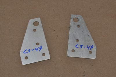
During all that time, I did manage to manufacture a few more small parts. I made several more brackets and three push-pull rods, two for the ailerons and one for the rudder. (Click on any of the pictures to see larger versions.)
These aileron push-pull tubes run vertically at the back of the cabin, translating the motions of the control sticks up to the torsion tubes at the wing roots.
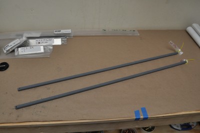
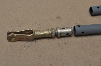
Most of the rest of the plane is aluminum but these tubes are steel so I have primed them to prevent rust. Since they will not be visible, this is probably all the “decoration” they will get. Other steel parts will be in plain sight, like the rudder pedals and control sticks. Those parts will get nice coats of gloss black over the primer.
With the completion of the aileron push-pull tubes, I was almost ready to begin assembling the control systems for the flight surfaces (ailerons, rudder, and horizontal stabilator). Pretty much the only pieces missing were the rudder pedals and the control sticks. Since assembly needs to proceed from the front of the plane to the rear, I had to wait for at least one of those parts to arrive.
While waiting, I took all of the small pieces that I have been making and attached them to their right places on the fuselage with clamps. Here are pictures, from the front of the cabin to the tail.
Looking into the cabin from the right side, you can see the cross member where the rudder pedals will attach. Tapes to this cross-member are some of the brackets for holding the rudder pedals. Right behind that, the rudder pedals are sitting on the floor. Further back is the cross member to which the control sticks will attach. Clipped to this cross-member are some of the brackets for holding the sticks (orange and blue clamps) and a guide for the rudder cables (purple clamp).
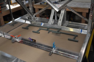
Turning and looking to the rear of the cabin, you can see the gear box, with the tops of the main landing gear legs inside. Taped to the front of the gear box are two brackets which will hold pieces of extruded angle that will run about 13″ forward to the cross-member for the control sticks. At the very back, you can see a guide for the push-pull tube for the horizontal stabilator, held in place with a light blue clamp.
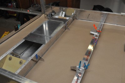
Looking aft from the cabin, you can see the guide for stabilator push-pull tube in the foreground and a larger contraption at the next cross-member. At that point, the small diameter steel push-pull tube ends and is connected to a larger diameter, lighter weight, aluminum push-pull tube which runs 7′ to the tail.
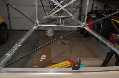
This photo gives you a closer view of the transition between the two push-pull tubes and, farther back, a guide for the larger tube (yellow clamps). The holes on the sides of the guide are for the cables for the rudder and the horizontal stabilator trim tab.
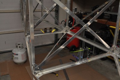
At the very back of the fuselage, almost hidden behind C-clamps, are a pair of brackets at which the rudder cables will end. The cables will attach to a steel see-saw like part that will translate the cables’ movement into a push-pull tube that will be attached to the base of the rudder.
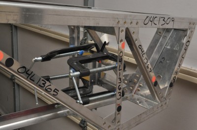
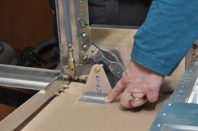
Returning to the rear of the cabin, you can see how the base of the aileron push-pull tubes will be attached. The control sticks will work cables which will be attached to the bell-crank in this picture and there will be a second tube on the other side of the plane.
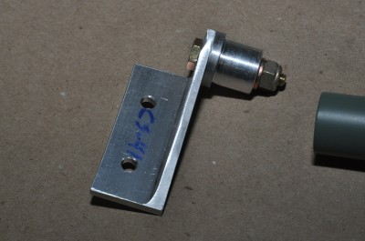
The BD-4C kit includes a 12″ long rod of .75″ diameter aluminum rod from which to machine a dozen rudder pedal end-caps. Fortunately, my friend Karsten made these for me. Sometimes a guy’s just gotta know a guy who’s got a lathe and knows how to use it! These end caps fit loosely into the rudder pedals and form a low tech “hinge.” Here you can see one of Karsten’s end caps bolted to one of my brackets.
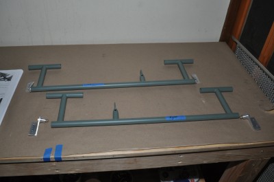
This picture gives you a better view of how the end-caps and brackets and rudder pedals all go together. Each steel bar has two pedals: one has the two left pedals and the other has the two right pedals. The little tabs in the middle of the bars are the attach points for the cables and springs.
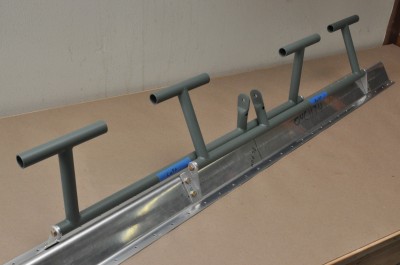
We are almost there. With the end-caps fabricated and attached to the brackets (which I made back on January 8), I bolted the rudder pedals to the cross-member that will hold them in the plane.
The whole assembly will get painted and then riveted to the floor at the front of the fuselage. But before any of that can happen, we had to test it. Candy was the first “pilot” to put her feet to the rudder pedals of our new plane.
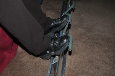
She even made appropriate airplane noises! 🙂

HI ART. WOW ON ALL THIS! YOU ARE DOING A BEAUTIFUL JOB!
ENJOY.
BOB.